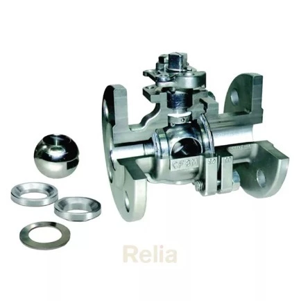
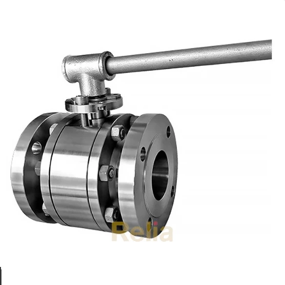
Ball Valve Hydraulic Testing Procedure
1. Hydrostatic Shell Testing:
- Preparation:
Valve ends shall be blocked and the closure member placed in the partially open position during the test.
When present, relief valves that release to the atmosphere shall be removed and their connection points plugged. Internal non-return valve shall be installed on sealant injection ports without the injection fitting.
- Test Pressure:
The test pressure for the hydrostatic shell test shall be a minimum of 1.5 times the pressure rating for material at 100 °F (38 °C) based on the valve end connector material.
- Test Duration:
The test duration shall conform to below table based on the valve end connector size.
Minimum Duration of Hydrostatic Shell Tests
| Valve Size | Test Duration a (minutes) | |
| NPS | DN | |
| ≤ 4 | ≤ 100 | 2 |
| 6 to 10 | 150 to 250 | 5 |
| 12 to 18 | 300 to 450 | 15 |
| 20 and larger | 500 and larger | 30 |
| FOOTNOTE a Test duration starts once the valve is stabilized per manufacturer’s procedures. | ||
- Acceptance Criteria:
There should be no visible leaks or weeping from the valve body or bonnet.
2. Hydrostatic Seat Testing:
Test Preparation, Method and Acceptance Criteria
- Test Preparation:
Lubricants or sealants shall be removed from seats and closure member sealing surfaces except where the lubricant or sealant is the primary means of sealing.
- Test Pressure:
The test pressure for all seat tests shall be a minimum of 1.1 times the pressure rating for material at 100 °F (38 °C) based on the valve end connector material.
- Test Duration:
The test duration shall conform to below table based on the valve end connector size.
Minimum Duration of Hydrostatic Seat Tests
| Valve End Connector Size | Test Duration a (minutes) | |
| NPS | DN | |
| ≤ 4 | ≤ 100 | 2 |
| 6 to 18 | 150 to 450 | 5 |
| 20 and larger | 500 and larger | 10 |
| FOOTNOTE a Test duration starts once the valve is stabilized per manufacturer s procedures. | ||
- Acceptance Criteria for Leakage
Seat leakage shall be monitored from the downstream side of the seat when under hydrostatic seat test. The acceptance criteria for leakage shall be as follows:
- For soft-seated ball valves: leakage shall not exceed ISO 5208, Rate A (no visible leakage for the duration of the test at test pressure).
- For metal-seated ball valves: leakage shall not exceed ISO 5208, Rate C.
On completion of hydrostatic seat testing, parts such as drain plugs and cavity-relief valves, shall be fitted in conformance with the manufacturer s documented procedures.
Table 4 — Maximum allowable closure test leakage rate
| Test fluid | Unit leakage rates | Rate A | Rate AA | Rate B | Rate C | Rate CC | Rate D | Rate E | Rate EE | Rate F | Rate G |
| Liquid | mm3/s | No visually detect- able leakage for the duration of the test | 0,006×DN | 0,01×DN | 0,03×DN | 0,08×DN | 0,1×DN | 0,3×DN | 0,39×DN | 1×DN | 2×DN |
| Drops/s | 0,0001×DN | 0,00016×DN | 0,0005×DN | 0,0013×DN | 0,0016×DN | 0,0048×DN | 0,0062×DN | 0,016×DN | 0,032×DN | ||
| Gas | mm3/s | 0,18×DN | 0,3×DN | 3×DN | 22,3×DN | 30×DN | 300×DN | 470×DN | 3000×DN | 6000×DN | |
| Drops/s | 0,003×DN | 0,0046×DN | 0,0458×DN | 0,3407×DN | 0,4584×DN | 4,5837×DN | 7,1293×DN | 45,837×DN | 9,1673×DN |
Unidirectional Ball Valve
Test Method:
With the valve half-open, the valve and its cavity shall be entirely filled with test fluid. The valve shall then be closed, and the test pressure applied to the appropriate end of the valve.
Leakage Monitoring:
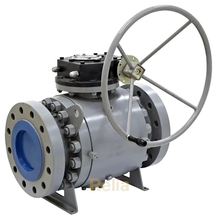
For trunnion ball valves, leakage from the upstream seat shall be monitored via the valve body cavity vent or drain connection, where provided.
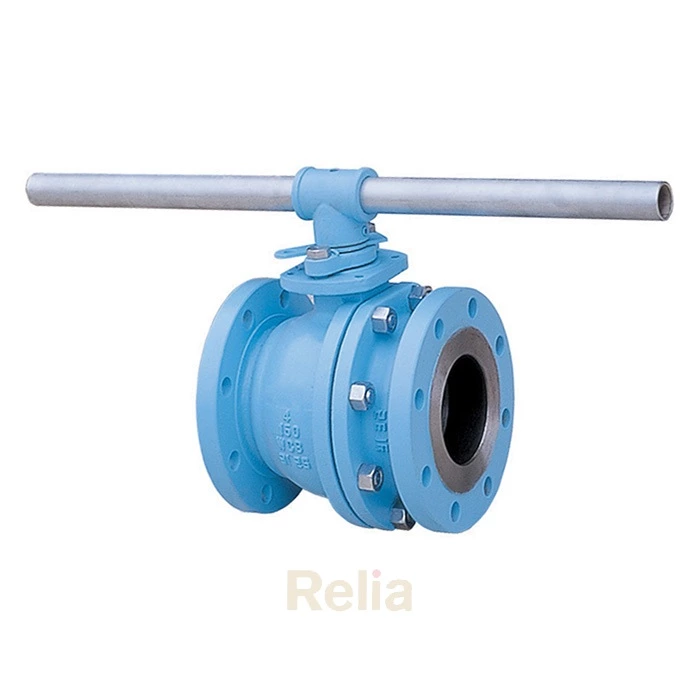
For floating ball valves, seat leakage shall be monitored at the respective downstream end of the valve (i.e., the valve end downstream of the pressurized test fluid).
Bidirectional Ball Valve
Test Method:
With the valve half-open, the valve and its cavity shall be entirely filled with test fluid. The valve shall then be closed, and the test pressure applied successively to both ends of the valve.
Leakage Monitoring:
For floating ball valves, seat leakage shall be monitored from each seat via the valve body cavity vent or drain connection, where provided.
For trunnion ball valves, seat leakage shall be monitored from the respective downstream end of the valve.
